SX-2000SM
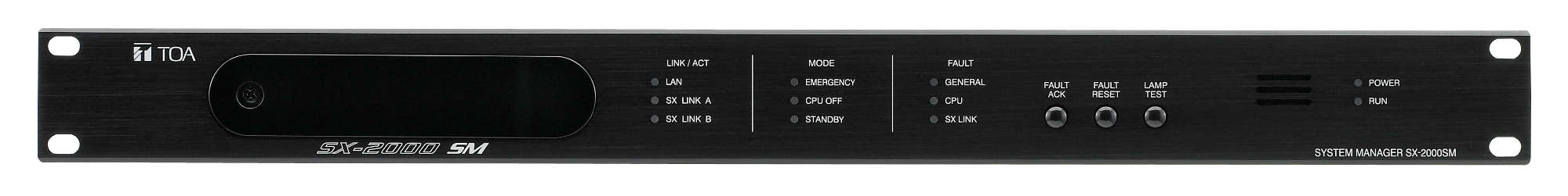
System Manager
SX-2000SM
The SX-2000SM System Manager is designed for use in TOA's Matrix System and can be mounted in an EIA Standard component rack (1-unit size). It can be used in combination with an optional audio input unit audio output unit and remote microphone of the SX-2000 Series to make up a complete matrix system and can perform audio signal routing and priority control for the entire system. The SX-2000SM itself is equipped with 8 control inputs, 8 control outputs, failure status outputs, failure data inputs/switches, access indicators, mode indicators and failure indicators enabling a wide range of controls and status monitoring. Control input line failure can be detected by connecting resistors to its line. The SX-2000SM has a function to supply a stabilized 24 V DC. Each control can be performed by way of a CF card inserted into the SX-2000SM unit. Operations of the entire system can be recorded and their contents stored on a CF card as an operation log. The SX-2000SM also features two power inputs making possible the creation of a dual-redundant power system. Equipped with two channels of interfaces for connecting to the Emergency Power Supply units, making it possible to configure the system to operate during a power failure.
- Matrix system in combination with an audio input unit, audio output unit and remote microphone
- Audio signal routing and priority control
- 8 control inputs, 8 control outputs
- Failure status outputs, failure data inputs/switches
- Access indicators, mode indicators and failure indicators enabling a wide range of controls and status monitoring
- Control can be performed by way of a CF card inserted into the SX-2000SM unit
- Operations can be recorded and their contents stored on a CF card as an operation log
- Two power inputs for creation of a dual-redundant power system
- Automatic voice announcement for emergency purpose available
- System settings via LAN connection
Power Source
Usable power supply unit: VX-200PS
24 V DC (operational range: 20 V - 40 V DC)
Two power inputs construction enables dual- redundant power supply.
24 V DC (operational range: 20 V - 40 V DC)
Two power inputs construction enables dual- redundant power supply.
Current Consumption
1.1 A or less (maximum value in the power operating range)
0.8 A or less (when operated on 24 V DC)
0.8 A or less (when operated on 24 V DC)
Indication/Operation
SX link access indicator: 2
LAN access indicator: 1
Mode indicator: 3 (EMERGENCY/STANDBY/ CPU OFF)
Failure indicator: 3 (GENERAL/CPU/SX LINK)
Power indicator: 1 (POWER)
Run indicator: 1 (RUN)
Failure control switch: 3 (ACK/RESET/LAMP TEST)
LAN access indicator: 1
Mode indicator: 3 (EMERGENCY/STANDBY/ CPU OFF)
Failure indicator: 3 (GENERAL/CPU/SX LINK)
Power indicator: 1 (POWER)
Run indicator: 1 (RUN)
Failure control switch: 3 (ACK/RESET/LAMP TEST)
SX Link
Network I/F
2 100BASE-TX circuits, RJ45 connector
Matrix System Specification
Bus: 16
Audio input: Max. 64 ch
Audio output: Max. 256 zones
Contact input: Max. 1416
Contact output: Max. 1416
Priority control: 512 steps
Event log: Up to 1,000 logs per file (up to 100 files available)
Failure log: Up to 100 logs per file (up to 100 files available)
Audio input: Max. 64 ch
Audio output: Max. 256 zones
Contact input: Max. 1416
Contact output: Max. 1416
Priority control: 512 steps
Event log: Up to 1,000 logs per file (up to 100 files available)
Failure log: Up to 100 logs per file (up to 100 files available)
Matrix System Configuration
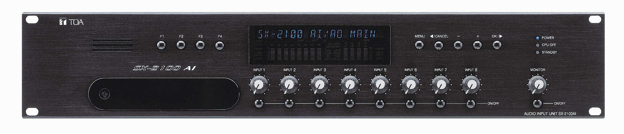
Connectable SX-2100AI No.: Max. 8 units
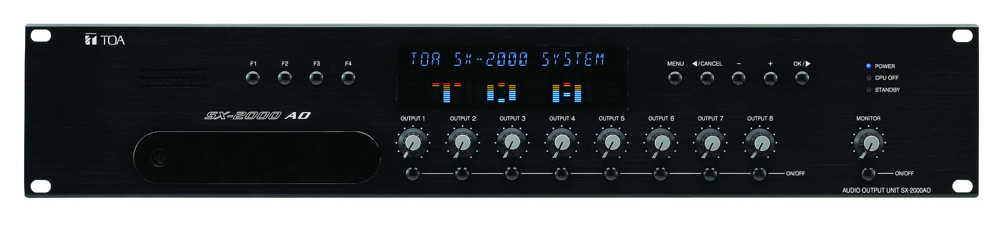
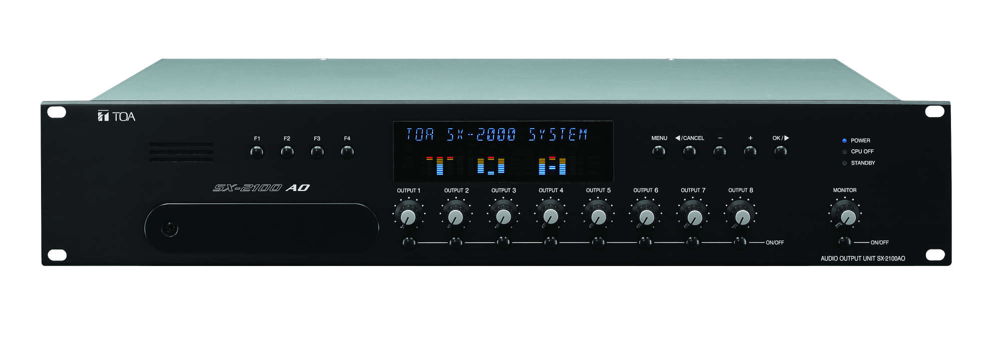
Connectable SX-2000AO/2100AO No.: Max. 32 units
Connectable SX-2000CI No.: Max. 32 units
Connectable SX-2000CO No.: Max. 32 units
Connectable RM-200SA/SF No.: Max. 64 units (up to 8 RM-200SA per SX-2100AI)
Connectable SX-2000AO/2100AO No.: Max. 32 units
Connectable SX-2000CI No.: Max. 32 units
Connectable SX-2000CO No.: Max. 32 units
Connectable RM-200SA/SF No.: Max. 64 units (up to 8 RM-200SA per SX-2100AI)
Connection Cable/Device
Shielded Category 5 twisted pair cable (CAT5-STP)
(Connect SX-2100AI and SX-2000AO/2100AO via the switching hub specified by TOA.)
Note: This network must be made completely independent from other LAN.
(Connect SX-2100AI and SX-2000AO/2100AO via the switching hub specified by TOA.)
Note: This network must be made completely independent from other LAN.
Number of Cascaded Switching Hub
Up to 7
LAN
Network I/F
1 10BASE-T/100BASE-TX circuit (selectable by automatic recognition), RJ45 connector for maintenance use
Network Protocol
TCP/IP
Analog Link
Input/Output Connector
Output: 2, RJ45 connector
DS Link
Connector/Cable
2 interface, RJ45 Connector, Shielded Category 5 twisted pair cable (CAT5-STP)
Failure Data Input
3 inputs (ACK/RESET/LAMP TEST), no-voltage make contact input, open voltage: 24V DC, short-circuit current: 2 mA, photo coupler input, removable terminal block (12 pins)
Failure Data Output
4 outputs (CPU FAULT/GENERAL FAULT/CPU OFF/BUZZER), Form C contact, no-voltage make contact output, relay contact output (with stand voltage: 40V DC, control current: 2 - 300 mA), RJ45 connector
Control Input
8 inputs, no-voltage make contact input, open voltage: 24 V DC, short-circuit current 2 mA, photo coupler input, removable terminal block (12 pins)
Surveillance Section for the Control Input Lines
Connection resistance to make the function inactive: 20 kΩ, ±5%
Connection resitance to make the function active: 10 kΩ ±5%
Connector cable: Twisted pair cable (shielded type is recommended)
Maximum cable distance : 10 m
Connection resitance to make the function active: 10 kΩ ±5%
Connector cable: Twisted pair cable (shielded type is recommended)
Maximum cable distance : 10 m
Control Output
8 outputs, Form C contact, no-voltage make contact output, relay contact output (withstand voltage: 40 V DC, control current: 2 - 300 mA), removable terminal block (12 pins)
24 V DC Output
Output Voltage
24 V DC ±10 % or less
Maximum Feeding Current
100 mA
Memory Card
Insertion slot: 1 (use of supplied CF card (128 MB), set data and log data stored
Operating Temperature
0 °C to +40 °C
Operating Humidity
35 % to 80 % RH (no condensation)
Finish
Panel: Aluminum, black, alumite
Case: Surface-treated steel plate
Case: Surface-treated steel plate
Dimensions
482 (W) x 44 (H) x 333 (D) mm
Weight
3.8 kg
Included Accessories
CD (PC setting software) x 1, EV-CF128M (CF card) x 1, Rack mounting screw x 4, Removable terminal pluc (4 pins) x 1, Removable terminal plug (12 pins) x 4, Driver x 1
Please download Datasheet to access full specifications.

System Manager, central control unit of the voice alarm system for installation in 19-inch cabinet racks (IEC 60297).
Separate ads for:
-Mode: emergency/standby/analog reserve way
-Activity LAN connection
-Activity of the audio and control network
-Errors: General/CPU/audio and control network
-Power supply
-Operation
Separate buttons for:
-Acknowledgement of fault messages
-Resetting the fault signal
-Lamp test
Acoustic warning in case of a malfunction in accordance with the relevant standards for voice alarm systems.
Redundant power supply for reliable power supply. Two network connections (100BaseTX) for redundant network for audio and control signals, additional analog reserve way. LAN connection to read the system activity, errors and operating conditions, as well as to set the system time. 8 Control inputs with opto-couplers and 8 control outputs with relay changeover contacts via pluggable connectors. Each input can be monitored either.
Two connectors for the monitoring of emergency equipment. Separate control outputs for the above mentioned error messages, E.g. to the forwarding and the BMZ.
The programming software included with the delivery.
Need other technical materials like software? Please visit Download Center.
*Sign-in or membership registration is required.
- Products
SX-2000SM