VX-3004F
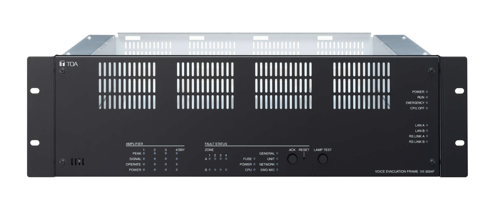
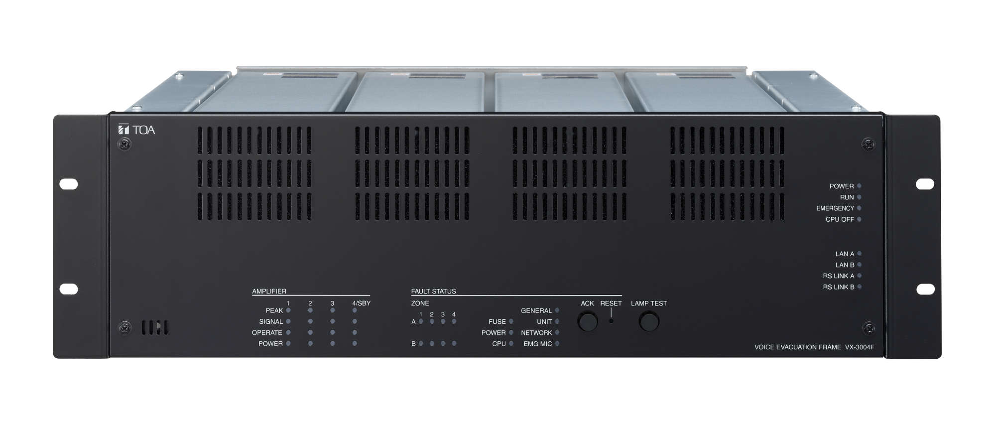
Voice Evacuation Frame
VX-3004F
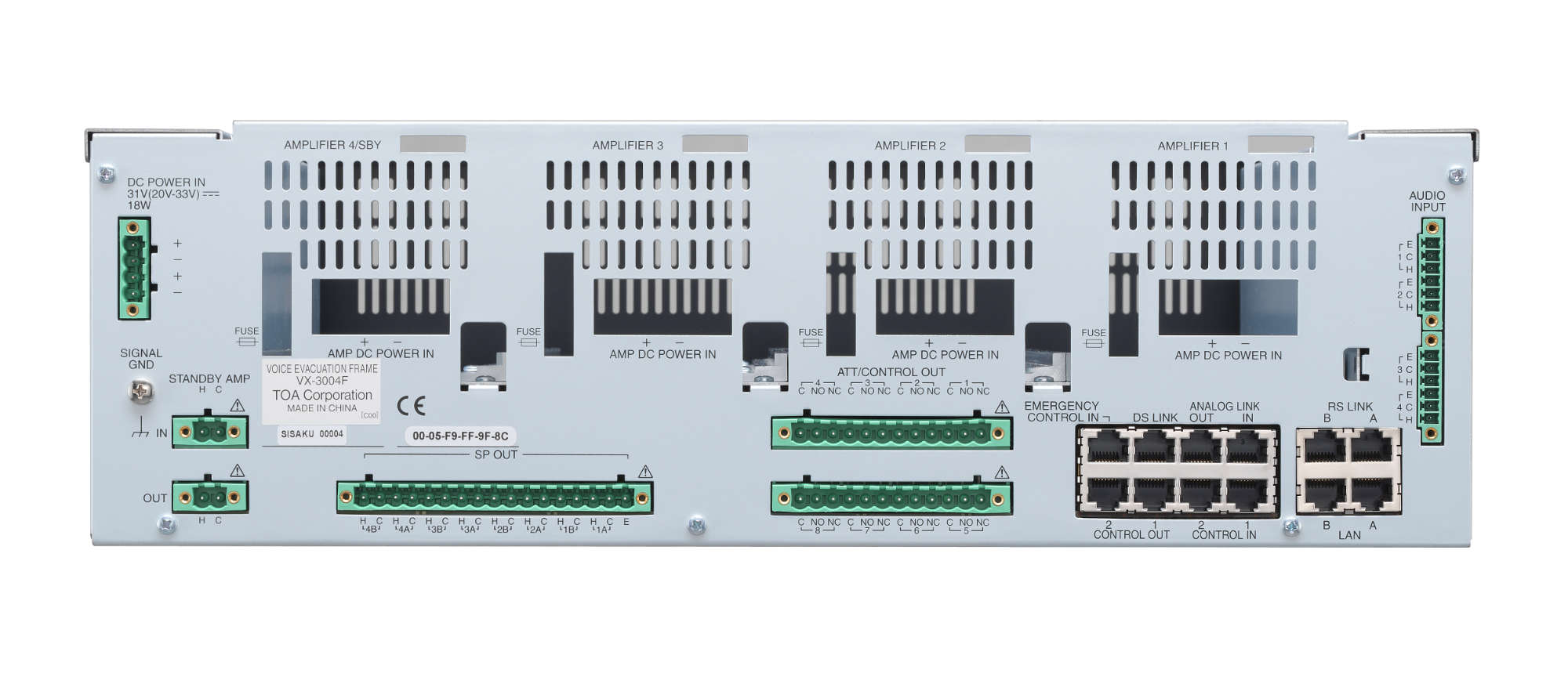
The VX-3004F is a device designed to control the voice evacuation announcements of TOA's VX-3000 Series rack-mount type voice evacuation system which is compliant with the European Standard EN54 for fire alarm systems. It has audio input terminals and can output the amplified audio signals to the speaker lines when the optional power amplifier modules are mounted.
It is possible to make an Emergency Warning Broadcast assigned a higher priority than the Emergency broadcast. Two patterns of the Emergency broadcast can be activated simultaneously. Compatible with network, the system can be configured in distributed arrangement.
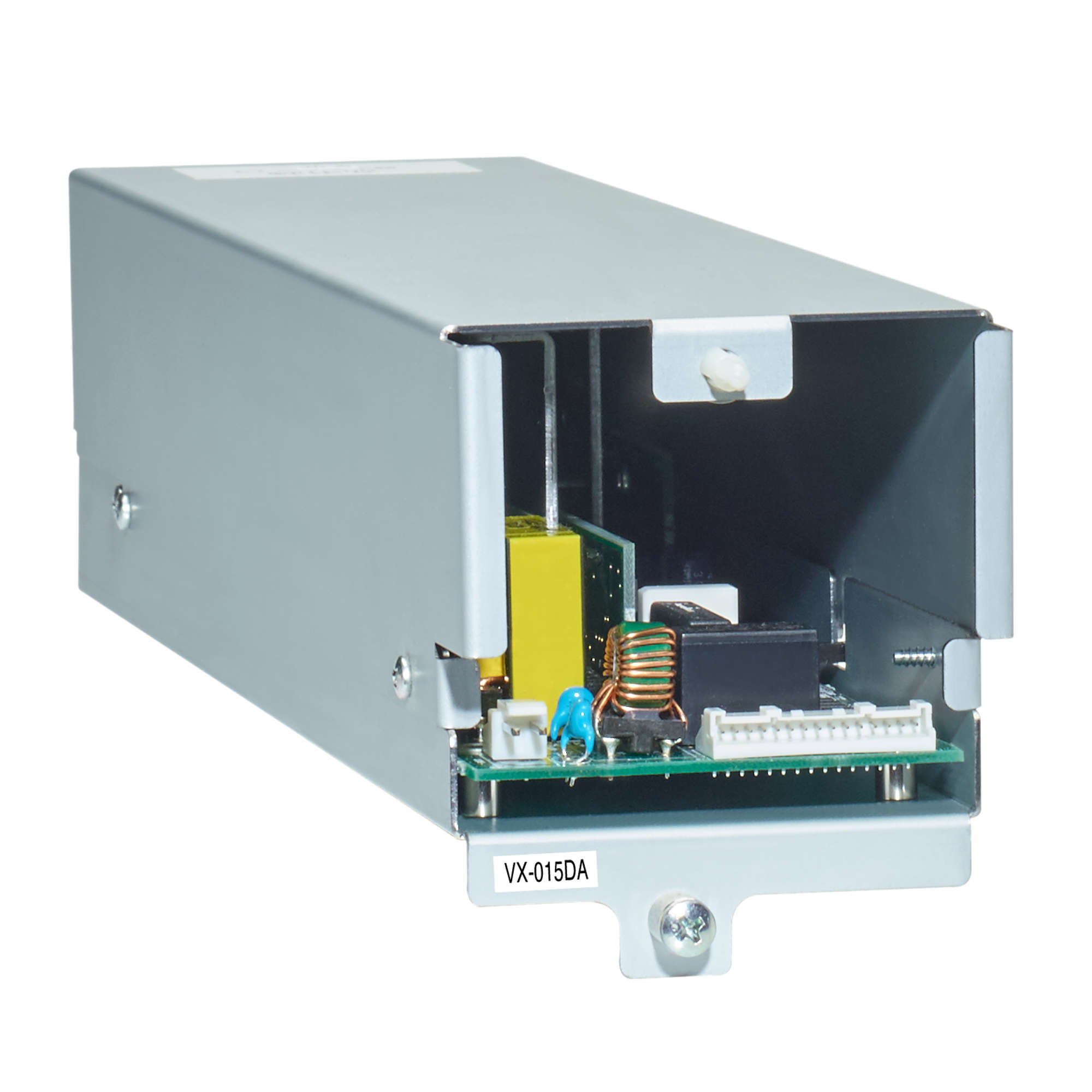
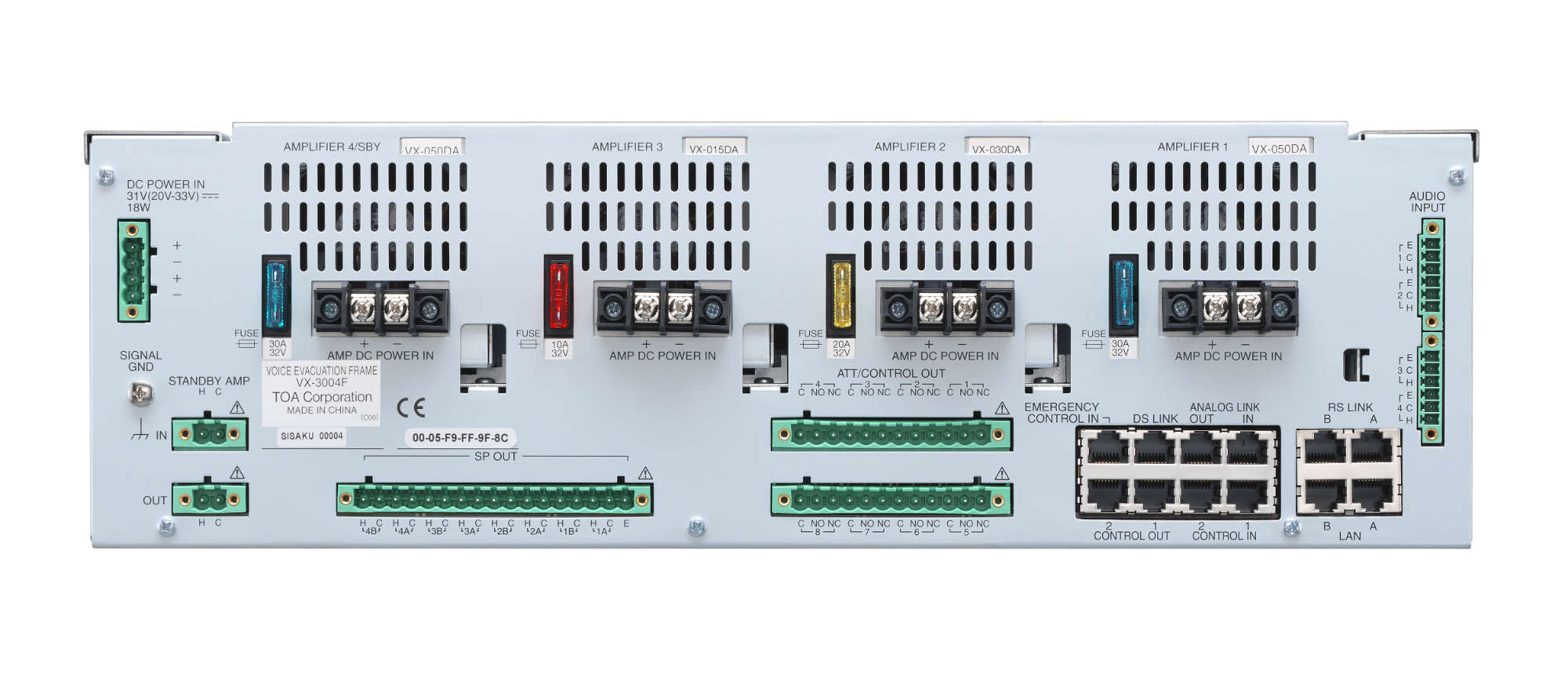
Features include the following functions: Digital signal processing function that enables appropriate acoustic adjustment for individual input sound sources and output areas, Feedback suppressor function that automatically suppresses acoustic feedback when it occurs, VOX function that allows start/stop control of broadcast by way of an audio trigger, and ANC function that enables an ambient noise control. (The ANC function distinguishes between the unit's output sound and the ambient noise. The unit's output sound is not detected as noise.) Indicators that show such statuses as fault status and power amplifier signal status are provided. It has 4 speaker output channels, each of which is provided with A and B lines to enable duplication of the speaker lines. Up to 4 power amplifier modules can be mounted. The 4-channel amplifier can be used either for zone output or standby use. As the VX-3004F is equipped with Standby amplifier input/output terminal, the standby amplifier, when mounted, can be shared among VX-3000F units.
- Up to 4 amps (1 zone - 1 amp, 4 AB-zones or 3 AB zones + standby amp)
- All mandatory indications by EN54-16
- Status indication for each speaker line
- Fault acknowledge and lamp test button
- Input DSP: flexible filtertypes and compressor
- Output DSP: flexible filtertypes, compressor and delay up to 2.7 sec.
Power Source
20 - 33 V DC, removable terminal block (4 pins)
Power Consumption
24 W (frame only) at 33 V DC input, 90 W (RS LINK: 2 A output) at 33 V DC input
LAN A, B
Number of Connectors: 2 (LAN A, LAN B)
Network I/F: 100BASE-TX
Network Protocol: TCP, UDP, ARP, ICMP, RTP, IGMP, FTP, HTTP, NTP
Spanning tree Protocol: RSTP
Audio Transmission System: TOA Packet Audio*1
Audio Encoding Method: PCM
Audio Sampling Frequency: 48 kHz
Audio Quantifying Bit Number: 16 bits
Connection Device: VX-3004F, VX-3008F, VX-3016F, NX-300, VX-3000PM, VX-3000CT, Switching HUB
Connector: RJ45 connector
Connection Cable: Category 5 twisted pair cable (CAT5) or greater
Number of Stages of Cascade connection:Up to 7
Maximum Cable Distance: 100 m (328.08 ft)
RS Link A, B
Number of Connectors: 2 (RS LINK A, RS LINK B)
Audio input level: 0 dB (*2) Power feed: Max. 1 A per connector Connector: RJ45 connector
Connection Cable: Shielded Category 5 twisted pair cable (CAT5) or greater
Maximum Cable Distance: 1200 m (3937.01 ft)
Audio input level: 0 dB (*2) Power feed: Max. 1 A per connector Connector: RJ45 connector
Connection Cable: Shielded Category 5 twisted pair cable (CAT5) or greater
Maximum Cable Distance: 1200 m (3937.01 ft)
DS Link
Connection Device: DS LINK of Power supply units
Connector: RJ45 connector
Connection Cable: Shielded Category 5 twisted pair cable (CAT5-STP) or greater
Maximum Cable Distance: 5 m (16.4 ft)
Connector: RJ45 connector
Connection Cable: Shielded Category 5 twisted pair cable (CAT5-STP) or greater
Maximum Cable Distance: 5 m (16.4 ft)
Analog Link
Number of Connectors: 1 input, 1 output
Connection Device: VX-3004F, VX-3008F, VX-3016F
Connector: RJ45 connector
Connection Cable: Shielded Category 5 twisted pair cable (CAT5-STP) or greater
Maximum Cable Distance: 800 m (2624.67 ft)
Connection Device: VX-3004F, VX-3008F, VX-3016F
Connector: RJ45 connector
Connection Cable: Shielded Category 5 twisted pair cable (CAT5-STP) or greater
Maximum Cable Distance: 800 m (2624.67 ft)
Audio Input 1, 2, 3, 4
4 inputs
Sensitivity:
LINE: −20 dB*2, MIC: −60 dB*2
LINE/MIC/ANC Sensor (changeable with setting software)
Gain Control: volume adjustable with volume control (internal front panel) −∞ to 0 dB
Input Impedance: 47 kΩ, electronically-balanced
Frequency Response: 40 Hz to 20 kHz ±1 dB (at DA CONTROL LINK, 0 dB output)
Distortion: 1% or less (at DA CONTROL LINK, 0 dB output, 1 kHz)
Signal to Noise Ratio: 60 dB or more (at DA CONTROL LINK, A-weighted)
Phantom Power Supply: 24 V DC, can be set with setting software
Connector: Removable terminal block (6 pins) x 2
Control Input 1, 2
16 inputs, no-voltage make contact input, open voltage: 24 V DC, short-circuit current: 2 mA,
Fault Detection System: Short circuit, Open circuit, Method: Voltage detect
Connector: RJ45 connector,
Connection Cable: Shielded Category 5 twisted pair cable (CAT5-STP) or greater
Fault Detection System: Short circuit, Open circuit, Method: Voltage detect
Connector: RJ45 connector,
Connection Cable: Shielded Category 5 twisted pair cable (CAT5-STP) or greater
Emergency Control IN
Input 2: Isolated voltage input, −24 to +24 V
Connector: RJ45 connector
Connection Cable: Category 5 twisted pair cable (CAT5) or greater
Connector: RJ45 connector
Connection Cable: Category 5 twisted pair cable (CAT5) or greater
VOX Function
Threshold: –60 to 0 dB (1 dB steps)
Hysteresis: 0 to +10 dB, Hold time: 10 ms – 10 s
Settable for each audio input
Hysteresis: 0 to +10 dB, Hold time: 10 ms – 10 s
Settable for each audio input
Control Output 1, 2
General outputs: 8 with CONTROL OUTPUT 1
Exclusive outputs: 3 with CONTROL OUTPUT 2 GENERAL FAULT, CPU FAULT, CPU OFF)
No-voltage make contact, electrical contact output, control current: 10 mA, withstand voltage: 28 V DC
Connector: RJ45 connector
Connection Cable: Shielded Category 5 twisted pair cable (CAT5-STP) or greater
Exclusive outputs: 3 with CONTROL OUTPUT 2 GENERAL FAULT, CPU FAULT, CPU OFF)
No-voltage make contact, electrical contact output, control current: 10 mA, withstand voltage: 28 V DC
Connector: RJ45 connector
Connection Cable: Shielded Category 5 twisted pair cable (CAT5-STP) or greater
ATT/Control Output
8 outputs, no-voltage make contact, relay contact (NC, NO, C),
control current: 2 mA to 5 A, withstand voltage: 125 V AC, 40 V DC
Connector: Removable terminal block (12 pins) x 2
control current: 2 mA to 5 A, withstand voltage: 125 V AC, 40 V DC
Connector: Removable terminal block (12 pins) x 2
Digital Signal Processing
Feedback Suppression Function (FBS)
7 filters (auto),
Settable for each audio input and RS LINK (A/B)
Settable for each audio input and RS LINK (A/B)
Equalizer/Filter
3 bands for each audio input and RS LINK (A/B), 6 bands for each amplifier output
Parametric equalizer: 20 Hz – 20 kHz, ±15 dB, Q: 0.267 – 69.249
Filtering: High-pass filter 20 Hz – 20 kHz, 6 dB/oct, 12 dB/oct
Low-pass filter 20 Hz – 20 kHz, 6 dB/oct, 12 dB/oct
High shelving filter 6 – 20 kHz, ±15 dB
Low shelving filter 20 – 500 Hz, ±15 dB
Notch filter (amplifier output only) 20 Hz – 20 kHz, Q: 8.651 – 69.249
All-pass filter (amplifier output only) 20 Hz – 20 kHz, Q: 0.267 – 69.249
Horn equalizer (amplifier output only) 20 kHz, 0 to +18 dB (0.5 dB steps)
Compressor
Threshold: –20 to 0 dB (1 dB steps)
Ratio: 1:1, 1.1:1, 1.2:1, 1.3:1, 1.5:1, 1.7:1, 2:1, 2.3:1, 2.6:1, 3:1, 4:1, 5:1, 7:1, 8:1, 10:1, 12:1, 20:1, ∞:1
Attack time: 0.2 ms – 5 s
Release time: 10 ms – 5 s
Gain: –∞ to +10 dB
Knee type: hard knee, middle knee, soft knee
Ratio: 1:1, 1.1:1, 1.2:1, 1.3:1, 1.5:1, 1.7:1, 2:1, 2.3:1, 2.6:1, 3:1, 4:1, 5:1, 7:1, 8:1, 10:1, 12:1, 20:1, ∞:1
Attack time: 0.2 ms – 5 s
Release time: 10 ms – 5 s
Gain: –∞ to +10 dB
Knee type: hard knee, middle knee, soft knee
Delay
For each amplifier output, 0 – 2730 ms (0.021 ms steps)
ANC (Ambient Noise Control)
Amplifier output level control, Automatic sensor input reference level measuring,
Sensor input reference level fine adjustment
Maximum output signal level control: –15 to 0 dB
Minimum output signal level control: –18 to –3 dB
Sample time setting: 10 s, 20 s, 30 s, 1 min, 5 min
Gain ratio setting: (Ambient noise: Output signal level) 6:3, 5:3, 4:3, 3:3, 3:4, 3:5, 3:6
Ambient noise measuring frequency setting: 20 Hz – 20 kHz, 3 points
Program Timer
Weekly program method
Daily program: 50 events, 10 types
Holiday program: 50 types
Daily program: 50 events, 10 types
Holiday program: 50 types
Time Adjustment
Control input, NTP
Speaker Line
4 channels (with A/B LINE speaker output), 1 Earth terminal
Maximum Voltage/Current: 100 Vrms, 5 Arms
Connector: Removable terminal block (17 pins) ... 1
Fault Detection System: Short circuit, Open circuit, Ground fault,
Method: Impedance or End of line
Maximum Voltage/Current: 100 Vrms, 5 Arms
Connector: Removable terminal block (17 pins) ... 1
Fault Detection System: Short circuit, Open circuit, Ground fault,
Method: Impedance or End of line
Standby Amplifier Input/Output
Input: 1, Output: 1
Maximum Voltage/Current: 100 Vrms, 5 Arms
Connector: Removable terminal block (2 pins) x 2
Maximum Voltage/Current: 100 Vrms, 5 Arms
Connector: Removable terminal block (2 pins) x 2
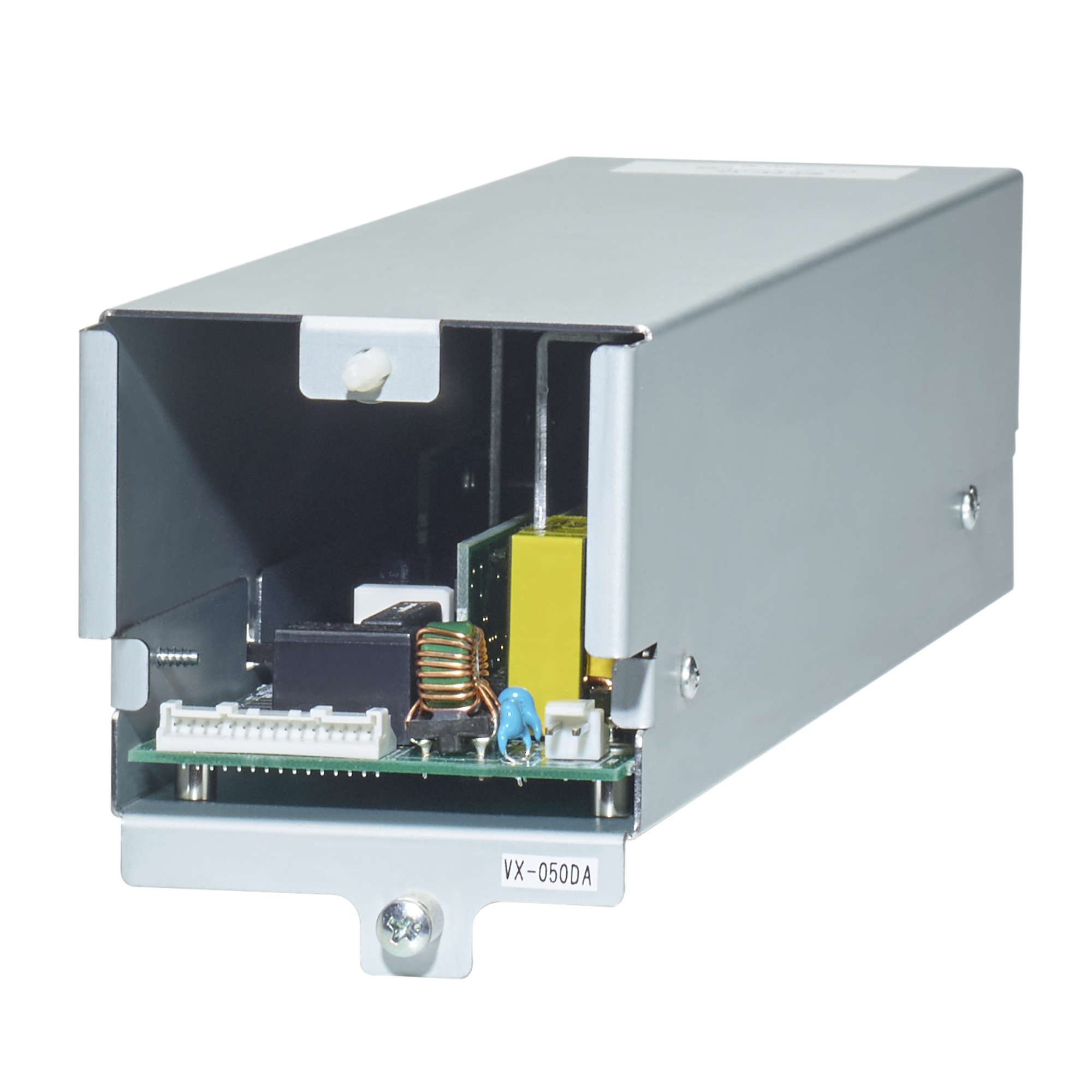
Module Slot
Number of modules: 4
DA CONTROL LINK x 4,
DA OUTPUT LINK x 4 (Used only when a power amplifier module is installed)
DA CONTROL LINK x 4,
DA OUTPUT LINK x 4 (Used only when a power amplifier module is installed)
Indicators
POWER (green) x 1, RUN (green) x 1, EMERGENCY (red) x 1, CPU OFF (red) x1, LAN A (green) x 1, LAN B (green) x 1, RS LINK A (green) x 1, RS LINK B (green) x 1
FAULT STATUS (yellow): GENERAL x 1, UNIT x 1, NETWORK x 1, EMG MIC x 1, FUSE x 1, POWER x 1, CPU x 1, ZONE x 8
AMPLIFIER: PEAK (red) x 4, SIGNAL (green) x 4, OPERATE (green) x 4, POWER (green) x 4
FAULT STATUS (yellow): GENERAL x 1, UNIT x 1, NETWORK x 1, EMG MIC x 1, FUSE x 1, POWER x 1, CPU x 1, ZONE x 8
AMPLIFIER: PEAK (red) x 4, SIGNAL (green) x 4, OPERATE (green) x 4, POWER (green) x 4
Operation
Fault Control Switch x 2 (ACK/RESET)
Test Switch x 1 (LAMP TEST)
Setting Switch: ID NUMBER, RESET, IMPEDANCE, Setting (internal front panel)
Test Switch x 1 (LAMP TEST)
Setting Switch: ID NUMBER, RESET, IMPEDANCE, Setting (internal front panel)
Operating Temperature
−5 °C to +45 °C (23 °F to 113 °F)
Operating Humidity
90% RH or less (no condensation)
Finish
Panel: Surface-treated steel plate, black, 30% glossy, paint
Dimensions
483 (W) x 132.6 (H) x 345 (D) mm (19.02" x 5.22" x 13.58")
Weight
7.6 kg (16.75 lb)
Included Accessories
Rack mounting screw x 4, Removable terminal plug (2 pins) x 2, Removable terminal plug (4 pins) x 1, Removable terminal plug (6 pins) x 2, Removable terminal plug (12 pins) x 2, Removable terminal plug (17 pins) x 1, CD (PC setting software) x 1, Ferrite clamp x 3
(*1) TOA's unique technology which makes it possible to trasmit high-quality autdio signals in real time over an IP network.
(*2) 0 dB = 1 V
(*3) Module: Digital power amplifier module, Line output module
(*2) 0 dB = 1 V
(*3) Module: Digital power amplifier module, Line output module
Please download Datasheet to access full specifications.
Frame for 4 amplifier modules with 4 monitored AB speaker outputs.
One amplifier module can optionally be configured as a standby amplifier.
Speaker line monitoring is possible by impedance surveillance or by using an end-of-line module.
Settings for impedance deviation to indicate an open or shorted line can be individually set for every output.
4 general balanced audio inputs (microphone/line level) and 2 inputs for up to 8 remote microphones including up to two emergency microphones.
The general audio signals of the audio inputs can be mixed.
All mandatory indications and controls regarding EN54-16 are on the front panel.
Fault indication for each speaker line.
Redundant network connection (Ethernet) of the frame with RSTP via two RJ45 ports.
Need other technical materials like software? Please visit Download Center.
*Sign-in or membership registration is required.
- Products
VX-3004F