SX-2100AO
Audio Output Unit
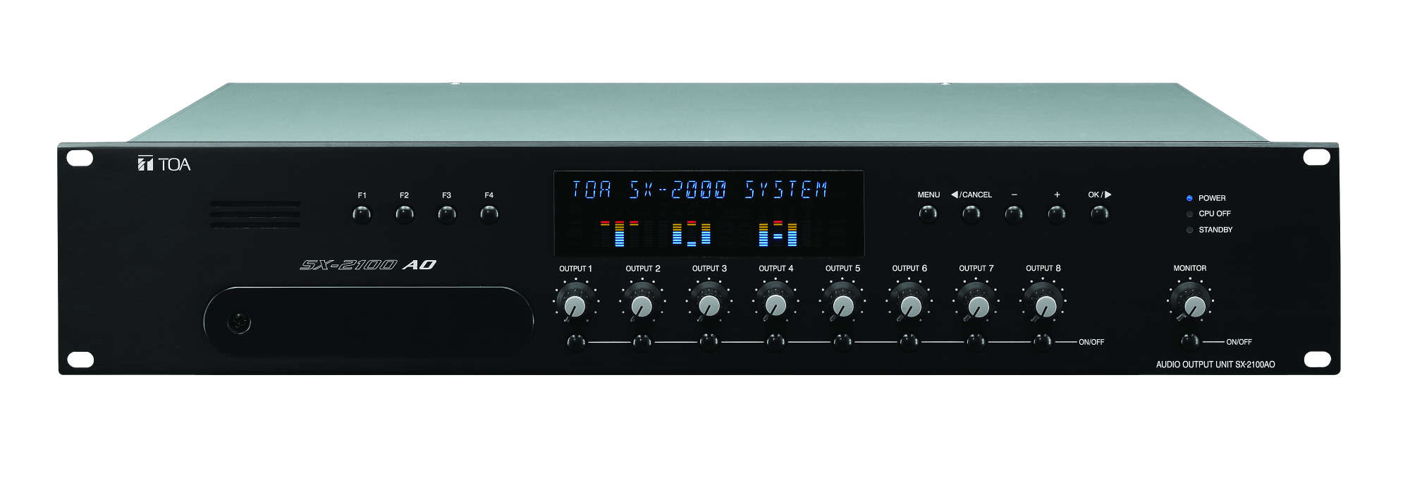
SX-2100AO
The SX-2100AO is an audio output of the matrix system and can be mounted in an EIA equipment rack (2 U size). Multiple units can be decentralized in a whole system. It is equipped with eight audio outputs, and two inputs can be mixed and output. It is also equipped with eight control inputs, and eight control outputs. The SX-2100AO receives audio signals from the audio input unit via digital transmission, but an analog audio input function (1 channel) enables simultaneous all-zone calls for use in emergency situations. Audio output levels are indicated on the level meters provided for each output channel. Volumes can be adjusted for each channel using the volume controls on the front panel or the SX-2000 software. The volume controls can be locked. Any output channel can be monitored using the internal speaker. Two channels of local audio inputs with control inputs are provided as the dedicated audio inputs. Its functions include an amplifier switching function that automatically switches the power amplifier to the standby amplifier if the power amplifier fails, and a surveillance function that self-diagnoses the speaker lines. Equipped with two channels of interfaces for connecting to the Emergency Power Supply units, making it possible to configure the system to operate during a power failure. One control IN/OUT interface allows the number of control inputs and outputs to be increased. The SX-2100AO has two power inputs and can support a dual-redundant power supply system.
- Multiple units can be decentralized in a system
- 8 audio outputs
- 8 control inputs and 8 control outputs
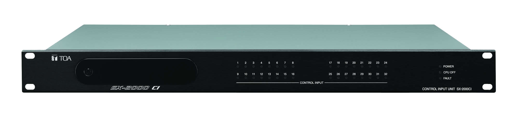
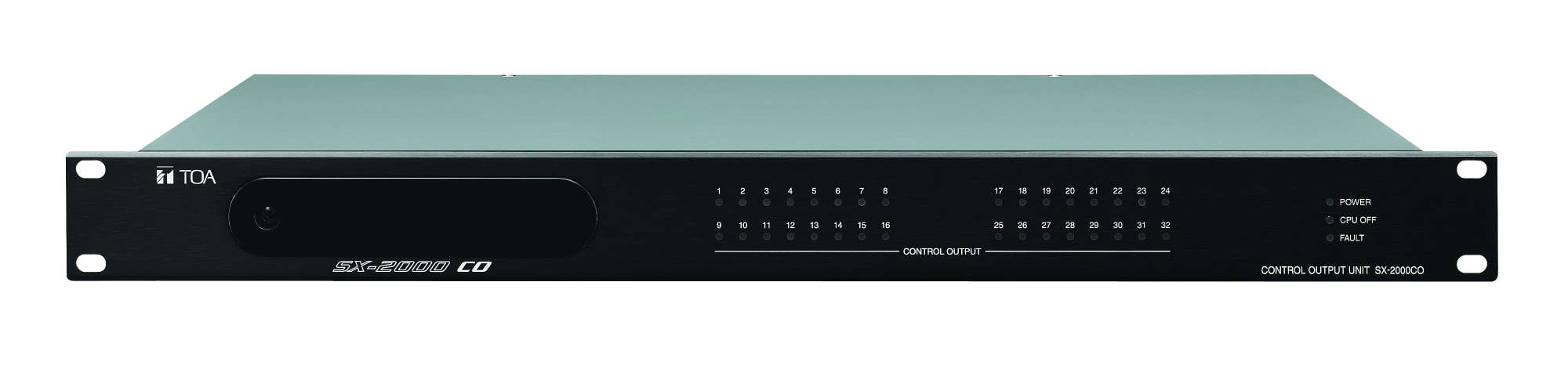
- 1 SX-2000CI Control Input Unit and 1 SX-2000CO Control Output Unit each can be cascaded
- 2 local audio inputs with control inputs are provided for the audio inputs
- Emergency switch over to a standby amplifier
- Analog transmission path (1 channel) enables all-zone calls for use in emergency situations
- 2 channels of link connection terminals for connecting to two VX-2000DS or VX-3000DS
- 2 inputs can be mixed and output
- 2 power inputs for redundant power supply
- Level meters for each output channel allow monitoring of audio output levels
- Output volumes adjustable on the front panel
- Any output channel can be monitored using the internal speaker
- Key lock function
- Automatic control of stand-by amplifier
Power Source
Usable power supply unit: VX-200PS
24 V DC (operational range: 20 V – 40 V DC)
Two power inputs construction enables redundant power supply.
24 V DC (operational range: 20 V – 40 V DC)
Two power inputs construction enables redundant power supply.
Current Consumption
Under 1.7 A (maximum value in the power operating range)
Under 1.2 A (when operated on 24 V DC)
Note: Excludes current consumption of the external equipment powered by the unit.
Under 1.2 A (when operated on 24 V DC)
Note: Excludes current consumption of the external equipment powered by the unit.
Indication
18 alphanumeric characters, Level indication (8 outputs, monitor),
Run indicator, Power indicator, Standby indicator, CPU OFF indicator
Run indicator, Power indicator, Standby indicator, CPU OFF indicator
Operation
Function keys, Output volume controls, Monitor volume control,
Channel keys, Monitor ON/OFF key, Menu screen operation keys
Channel keys, Monitor ON/OFF key, Menu screen operation keys
Audio Output Characteristic
8 outputs and standby AMP, 0 dB*, suitable load: 600 Ω or above,
electronically-balanced, monitoring possible using built-in speaker
Frequency response: 20 Hz – 20 kHz
Sampling frequency: 48 kHz
D/A converter: 24 bit
electronically-balanced, monitoring possible using built-in speaker
Frequency response: 20 Hz – 20 kHz
Sampling frequency: 48 kHz
D/A converter: 24 bit
Control Input
8 inputs, no-voltage make contact input, open voltage: Under 40 V DC,
short-circuit current: 2 mA, photo coupler input,
removable terminal block (6 pins)
short-circuit current: 2 mA, photo coupler input,
removable terminal block (6 pins)
Control Output
8 outputs, C contact, no-voltage make contact output: relay contact output
(withstand voltage: 40 V DC, control current: 2 – 300 mA),
removable terminal block (6 pins)
(withstand voltage: 40 V DC, control current: 2 – 300 mA),
removable terminal block (6 pins)
PA Link
Cable Requirements
RJ45 Connector, Shielded Category 5 twisted pair cable for LAN (CAT5-STP)
Maximum Cable Length
5 m
Compatible Amplifier
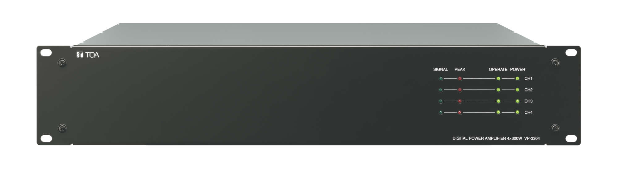
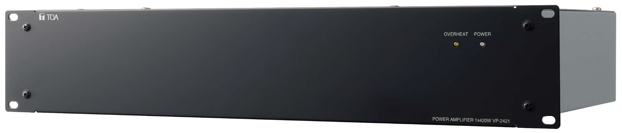
VP-2064, VP-2122, VP-2241, VP-2421, VP-3154 ,VP-3304, VP-3504
(VP-200VX is required for VP-2000 series amplifier)
(VP-200VX is required for VP-2000 series amplifier)
Local Audio Input
Audio Input
0 dB*, 10 kΩ, electronically-balanced
Audio Input Characteristic
Frequency response: 20 Hz – 20 kHz
Sampling frequency: 48 kHz
A/D converter: 24 bit
Sampling frequency: 48 kHz
A/D converter: 24 bit
Control Input
2 inputs, no-voltage make contact input, open voltage: 12 V DC,
short-circuit current: 2 mA, photo coupler input
short-circuit current: 2 mA, photo coupler input
Cable Requirements
2 inputs, RJ45 Connector,
Shielded Category 5 twisted pair cable for LAN (CAT5-STP)
Shielded Category 5 twisted pair cable for LAN (CAT5-STP)
SX Link
Network I/F
2 100BASE-TX circuits, RJ45 connector, decentralized installation possible
Connection Cable/Device
Shielded Category 5 twisted pair cable for LAN (CAT5-STP)
To be connected via the switching hub specified by TOA.
Note: This network must be made completely independent from other LAN.
To be connected via the switching hub specified by TOA.
Note: This network must be made completely independent from other LAN.
Maximum Cable Length
100 m (between this unit and a switching hub)
Analog Link
Input/Output Connector
Input: 1 input, RJ45 connector
Output: 1 output, RJ45 connector
Output: 1 output, RJ45 connector
Maximum Cable Length
800 m (total)
DS Link
Compatible Unit
VX-2000DS, VX-3000DS
Connector/Cable
2 interfaces, RJ45 Connector,
Shielded Category 5 twisted pair cable for LAN (CAT5-STP)
Shielded Category 5 twisted pair cable for LAN (CAT5-STP)
Maximum Cable Length
5 m
CI/CO Link
Compatible Unit
SX-2000CI or SX-2000CO
Connector/Cable
1 interface, RJ45 Connector,
Shielded Category 5 twisted pair cable for LAN (CAT5-STP)
Shielded Category 5 twisted pair cable for LAN (CAT5-STP)
Maximum Cable Length
800 m
Speaker Line Failure Detection Section
Connector/Cable
Removable terminal blocks, SP/AMP: 8 pins per terminal block,
STANDBY AMP: 2 pins, AWG 16 – 24
STANDBY AMP: 2 pins, AWG 16 – 24
Method
Impedance or End of line
End of Line
In Case of Normal: Terminated by 470 kΩ between the speaker line and the shield
In Case of Open: Opened between the speaker line and the shield
In Case of Open: Opened between the speaker line and the shield
Impedance
Minimum Load: 2 kΩ (5 W) at 100 V line
Operating Temperature
0°C ~ 40°C
Operating Humidity
35% to 80% RH (no condensation)
Finish
Panel: Aluminum, black, alumite
Case: Surface-treated steel plate
Case: Surface-treated steel plate
Dimensions
482 (w) x 88.4 (h) x 349 (d) mm
Weight
7.1 kg
Please download Datasheet to access full specifications.
Fully digital audio output unit for installation in 19-inch cabinet racks (IEC 60297) with 8 balanced audio outputs for connecting the amplifier of the VP-2000 series.
Two network connections (100BaseTX) for redundant network for audio and control signals, zusätz¬Licher analog reserve way. Redundant power supply for reliable power supply. 8 Control inputs with opto-couplers and 8 control outputs with relay contact, normally closed or normally open free choice, with removable terminal blocks. Two inputs for local audio sources to transfer in one or more programmable areas.
Large multicolored display on the front of the machine for:
-18-digit text display for system information
-Modulation bar indicator for each of the 8 channels
-Modulation bar indicator for two local inputs
-Status of each channel (on/off)
-Communication error of the network channels
-Collective fault signal
-Communication error (data line)
-Emergency mode
Buttons to select of the display of the system information. Four function keys to choose of pre-programmed music transfers or activating a transfers of a receipt on pre-programmed areas. 8 Channel keys to the switching on and off individual channels, optionally umprogrammierbar on activation of transmissions from an entrance on pre-programmed areas. Volume control for each channel, which is bridged for emergency-related transfers. Access to all the controls can be locked. Built-in monitor speakers with volume control to listen to each channel. 6 Can be freely selectable filter per channel (parametric equalizer, high and low-pass, all pass, CD-Horn equalizer, treble / bass control, notch filters), delay (delay) to 682 ms and compressor. Monitoring of all alarm-relevant signaling pathways including the connected amplifier and loudspeaker lines, CPU, power supply and network connections. Speaker line monitoring for short-circuit, break and Earth faults with intelligent, digital impedance control or with Linienendmodulen for each channel separately selectable. Adjustable tolerances for impedance deviation: short circuit: - 50% - 95%, interruption: + 1% to + 700%. Monitoring connection for two emergency power supply units. Control of the Energiespar¬modus of the amplifier to minimize the current drain of the battery during a power failure. Automatic switching to shipwreck amplifier an amplifier failure.
Need other technical materials like software? Please visit Download Center.
*Sign-in or membership registration is required.
- Products
SX-2100AO